Build
Introduction
This guide covers the construction of two variants of the OpenOBS:
- OpenOBS-328. A self contained turbidity and level sensor & logger.
- OpenOBS-Iridium. A bank-installed logger that can transmit data via Iridium satellite connection with a separate sensor deployed in the river.
Table of Contents
Logger Assembly
OpenOBS-328
The logger PCBs come mostly assembled. There are just 2 parts that need to be soldered to the back side of the board.
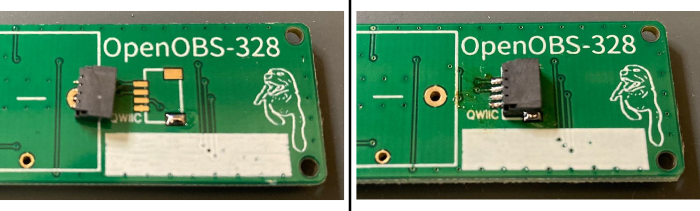
- Solder the QWIIC connector for the sensors. Start by adding a small dab of solder on one of the big corner pads. Let the solder solidify, and use some tweezers to grab the QWIIC connector. Remelt the solder with the iron and slide the connector in place, check that the metal legs on the back line up with the small gold pads. Solder these fine pads on the back, making sure not to short multiple pins together. If they do end up connected, try ‘swiping’ some of the solder away with a clean iron tip. If that isn’t working, then use a solder wick to remove some solder and try again. Solder the other corner pad (these give most of the mechanical strength).
-
Insert the battery holder on the back. There are markings on the board and the holder for positive and negative.
-
Flip the board over, solder the two battery holder legs, and cut off the excess.
-
Clean the residue from the solder flux around all the new joints using >90% isopropyl alcohol.
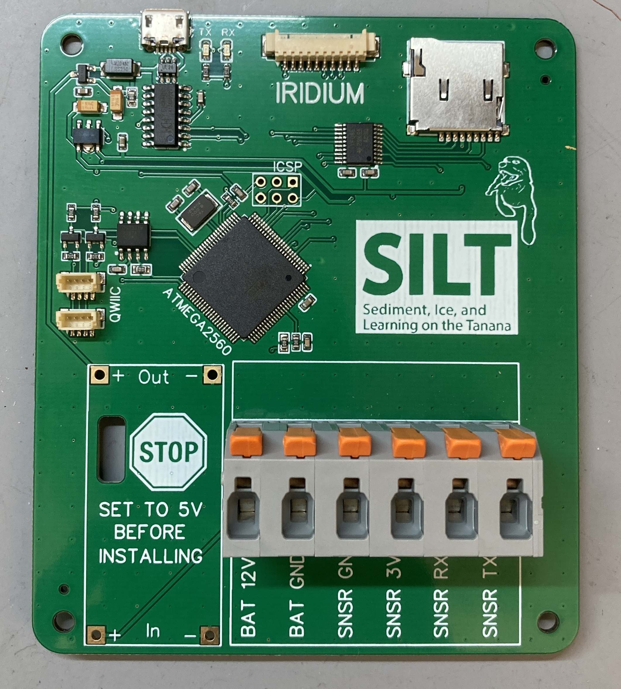
OpenOBS-Iridium
The Iridium logger PCBs come mostly assembled. There are just 2 parts that need to be soldered to the board.
-
Solder the WAGO wire connectors on with the levers facing towards the top of the board.
-
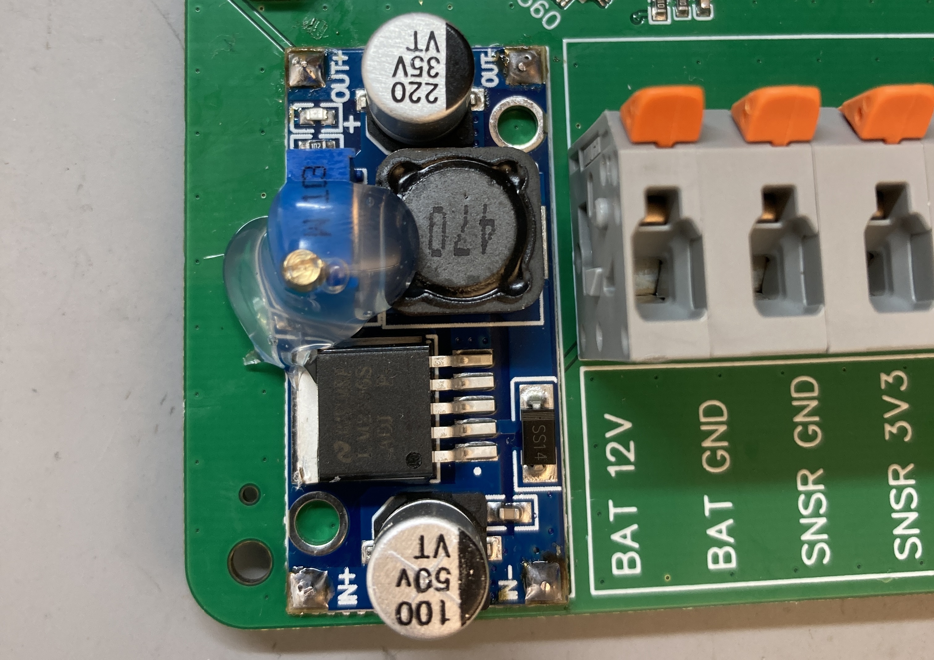
Next is the variable output buck converter for the 12V battery supply. As indicated on the PCB, we need to set the output to 5V before installing or we will let the smoke out of our electronics when we connect the battery!
-
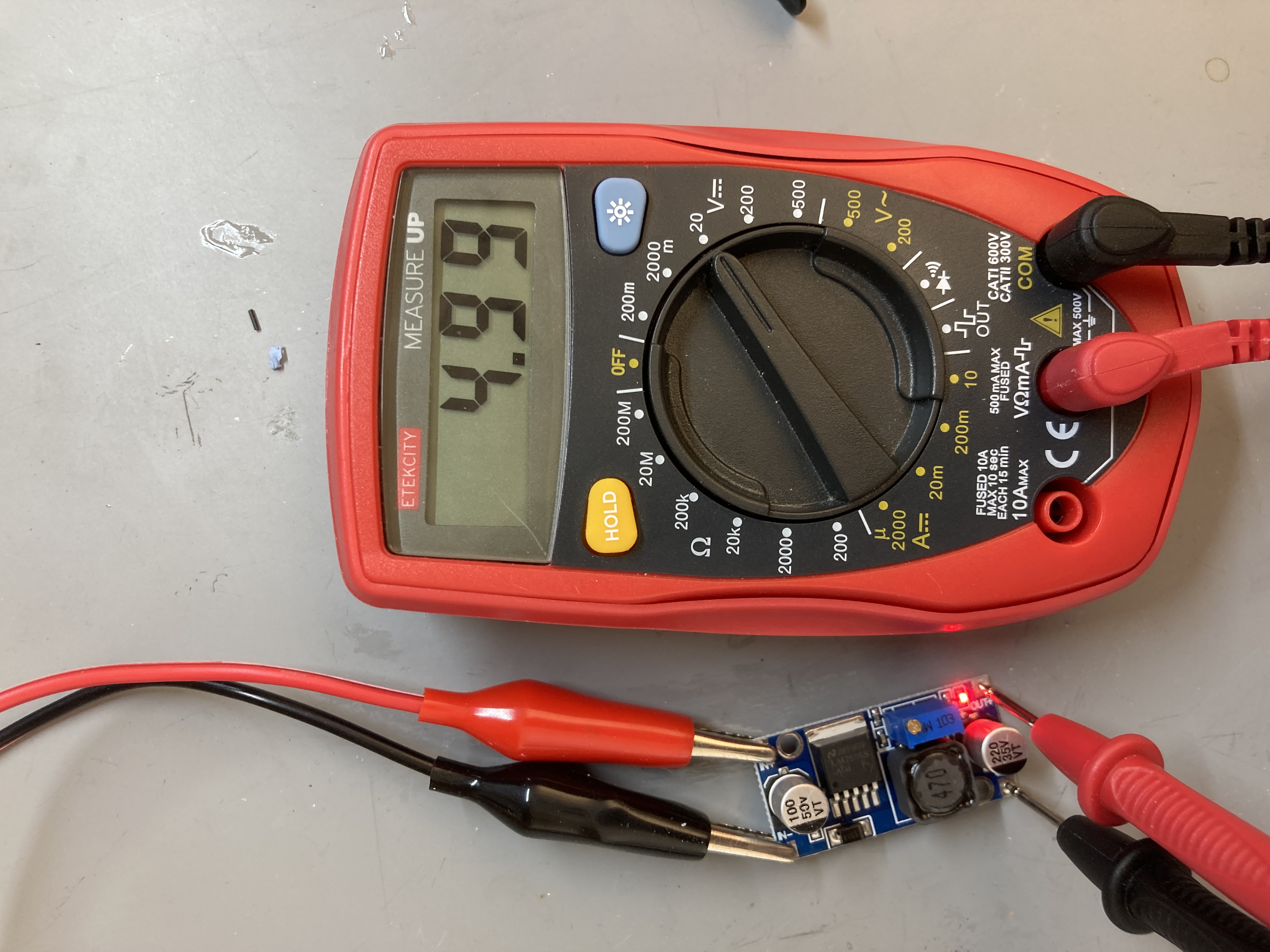
connect a 12V power supply or battery to the input of the buck converter using alligator clips. Measure the output with a multimeter and turn the potentiometer screw until it reads 5V +/- 0.05V. You will probably find they are set quite high from the factory and need several counter-clockwise turns before it even starts to decrease from the input voltage.
Bad! Good! 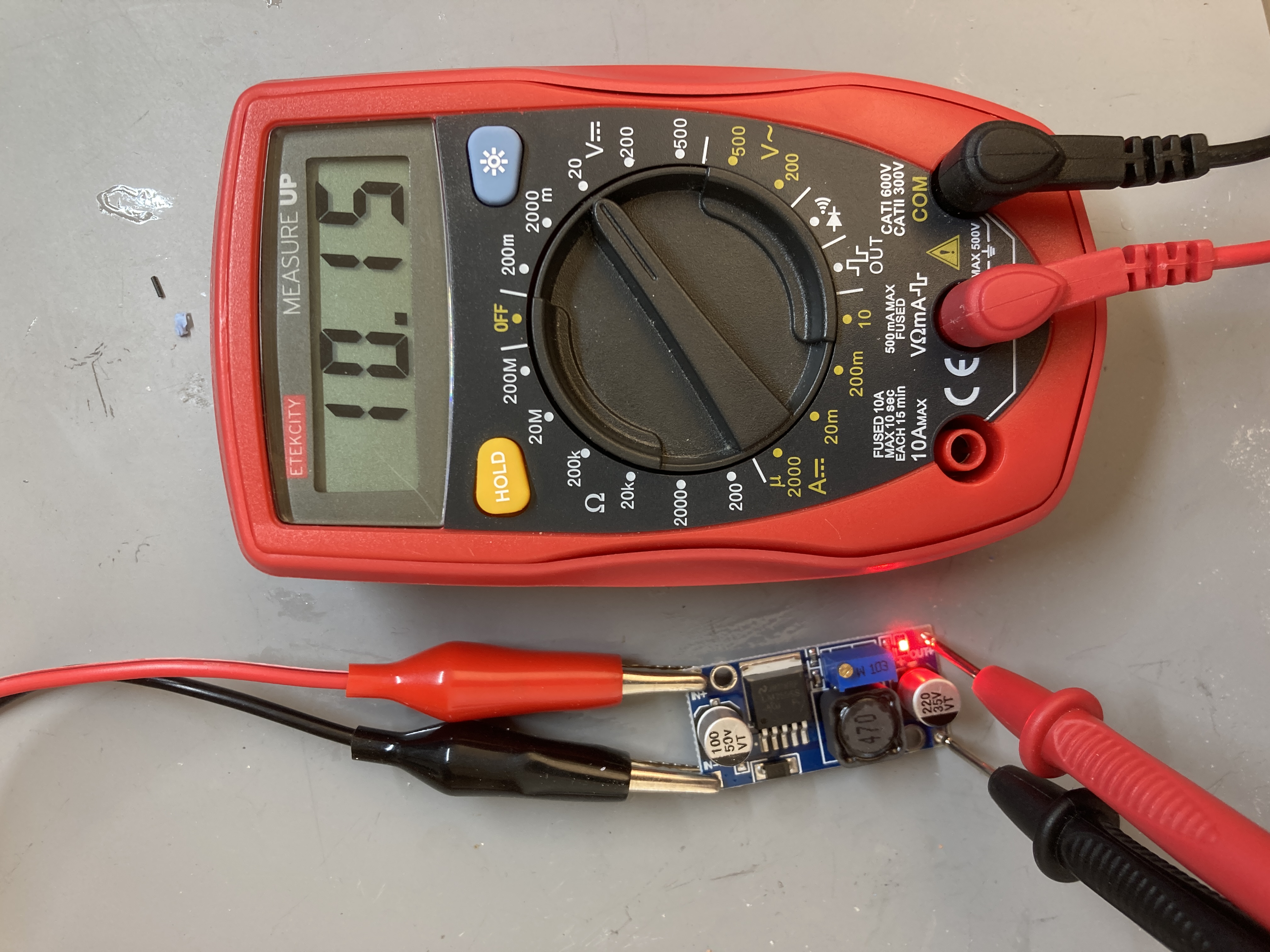
-
Remove the red LED that indicates the power is on. It will only waste power when deployed and is not needed.
- Orient the input and output of the buck converter on the PCB and solder the four corners. A bit of solid wire or old resistor leg can help transfer the heat and solder between the pads.
- Put a big glob of hot glue over the potentiometer to keep the screw set at 5V output.
-
Sensor Head
The sensor head is one of the OpenOBS end caps, and holds the proximity sensor and the pressure sensor. The sensor head has two chambers which are filled with clear epoxy. The epoxy makes the end cap watertight, and also allows light to travel between the proximity/turbidity sensor and the water.
3D printing housing
The sensor housing is produced by 3D printing. files located here.
Upload the .3mf file to the 3D printer’s interface and slice the file into machine code that can be printed. Printing settings will vary depending on your printer and materials. Here are the settings I use with a Prusa MK3S+ printer, the PrusaSlicer, and PETG filament:
- 0.2mm layer height
- 5 perimeters (greatly increases strength)
- External perimeters print first (better dimensional accuracy)
- Supports on the external overhangs only (internal overhangs can be bridged)
There is also a cap/filter for the pressure sensor to keep debris and sediment off the delicate white gel membrane.
Wiring
Pressure sensor
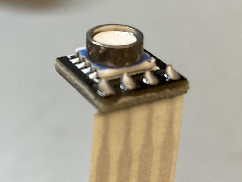
- Squeeze some solder paste on the pads of the SMD adapter board. The right amount of paste is more important than keeping the paste separate on each pad. The surface tension of the melted solder should ‘snap’ the puddles of solder onto the pads.
- Place the pressure sensor on the adapter board. Make sure the orientation is correct- there is a dot in one corner of both the adapter and the sensor that indicates orientation.
- Use a hot air gun at 250°C to heat both sides of the sensor and completely melt the solder. The paste is a mixture of solder balls and flux. You’ll see the flux move and smoke first but keep heating to melt the solder. Aim at one side and periodically rotate the board or move the hot air gun to avoid blowing hot air directly at the white gel cap. Sometimes the hot air pushes the sensor around; check that it is still in position before removing the heat.
-
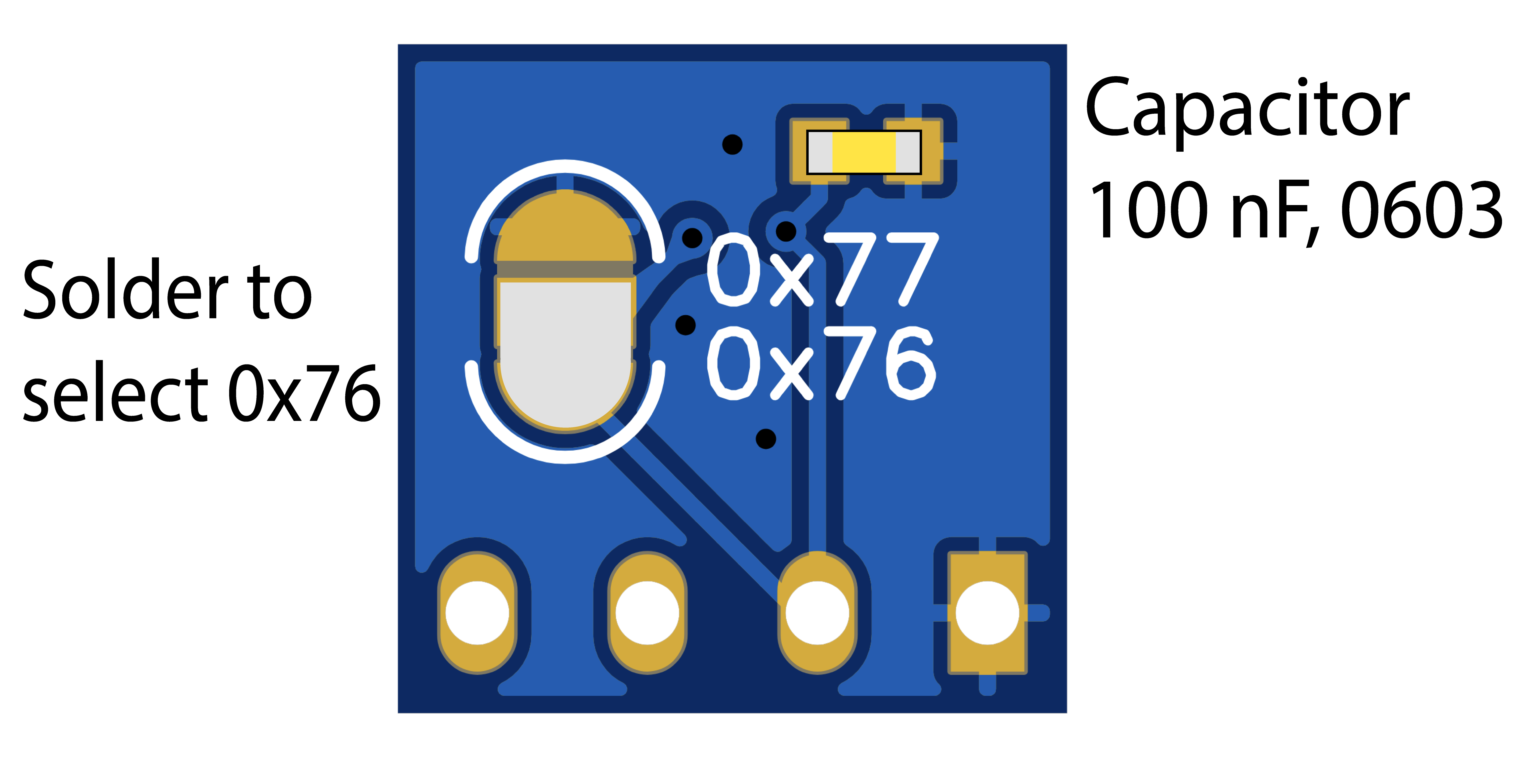
Flip the pressure sensor over to add a 100 nF capacitor and select the I2C address 0x76.
-
Solder the 4 pin flat flex cable in from the back of the PCB.
Turbidity sensor
- These steps are the same for both the OpenOBS-328 and the OpenOBS-Iridium except for this first step.
- OpenOBS-328: cut one of the 50 cm QWIIC cables in half (or use the other half from last time).
- OpenOBS-Iridium: cut another set of 6 cm long, 30 AWG wires in red, black, blue, and yellow.
- Separate the four strands and strip their ends.
- Put the pressure sensor assembly in the 3D printed sensor head
-
Solder the pressure sensor and turbidity sensor together using the set of 4 holes closer to the turbdity sensor. Make sure the orientation is correct so that the turbidity sensor slides into the housing facing out.
<img src="https://tedlanghorst.github.io/OpenOBS-328/assets/images/wiring_flatflex.JPG", width=50%>
-
Solder the QWIIC cable on to the other set of 4 holes towards the edge of the turbidity sensor.
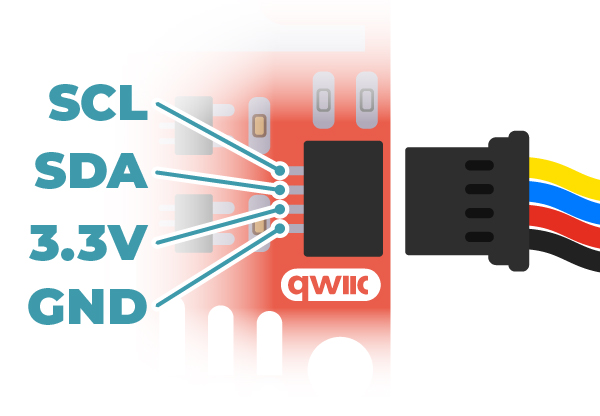
SCL yellow SDA blue 3V3 red GND black Image from Sparkfun
- Slide the proximity sensor into the head by pushing on the end of the PCB with a long flat tool. A scrap of protoboard works really well. It might take some force to get it all the way down, and if the tool slips off the PCB it’s very possible to break the wires you just soldered on.
- Finally, test the connections. If you are building an OpenOBS-328, you can simply plug the connector into one of the logger PCBs. If you have built the sensor with short bare wires for the OpenOBS-Iridium you can use alligator clips to connect to a test board. This is your last chance to fix anything before potting it in epoxy!
❓ If you don’t know how to check that the sensor is working, go to the programming section that covers uploading code to the logger and opening the serial monitor to read its output. Once you have a working logger you can just plug in each new sensor. If the logger starts up correctly and starts printing reasonable data you are good to continue!
Epoxy potting
Turbidity sensor
- The sensor head needs to be situated upside down in order to pour the epoxy. Place a shiny silicone pad or tuck tape (tyvek sheathing tape) between the sensor head and a flat surface (a granite countertop sample works well). The epoxy will not stick to the silicone pad and leaves a smooth surface.
-
Clamp or tape the sensor head securely to the slab. If you are doing more than a few sensors, I recommend printing this clamping caul that securely holdes 5 sensors at a time. If your printer does not have tight tolerances, you may have to increase the size slightly, there is only 0.2mm clearance.

Single sensor taped to a granite block. Stretching electrical tape gives enough pressure to stop leaks.
 3D printed clamping caul. This required a 3rd clamp in the middle to stop leaks.
 -
Prepare the epoxy by weighing out two parts Vivid Scientific Epoxy 128 (red label) and one part Epoxy 762 (green label) in a silicone or disposable weighing dish. One turbidity sensor requires only about 2 g Epoxy 128 and 1 g Epoxy 762. Thoroughly mix the two parts to ensure it cures fully.
- At this stage, the epoxy will contain bubbles, which will interfere with the optical path of the proximity sensor. Remove the bubbles by alternating between these two methods 2-3x until the epoxy is clear:
-
Vacuum chamber expands bubbles and brings them to the surface.
-
Heat gun reduces the viscosity of the epoxy, allowing bubbles to rise to the surface and burst.
⚠️ Although the heat setting for soldering purposes is 250 ℃, the heat gun should be set to ~120 ℃ when working with the epoxy. Too much heat will make the epoxy set rapidly.
 Epoxy just after mixing (left) and after the vacuum/heat process (right)
 -
-
Once the epoxy is bubble free, slowly pour it into the proximity sensor slot. The level of the epoxy should go above the proximity sensor window but below the opening for the pressure sensor- we don’t want epoxy dripping down on to the pressure sensor in this orientation. Allow the epoxy to cure for 12-24 hours before unclamping/removing tape.
<img src="https://tedlanghorst.github.io/OpenOBS-328/assets/images/epoxy_turbidity_final.png", width=50%>
Face of the turbidity sensor after curing (older version but similar).
Pressure sensor
- Use hot glue to seal the hole at the base of the pressure sensor slot. This will keep the epoxy from leaking down.
<img src="https://tedlanghorst.github.io/OpenOBS-328/assets/images/epoxy_pressure_plug.JPG", width=50%>
-
Set the sensor head upright so that the pressure sensor is facing up.
 A quick jig using scrap PVC to hold the sensor heads upright.
 - Prepare epoxy as in the previous section. Again, one sensor requires about 2g Epoxy 128 and 1g Epoxy 762.
-
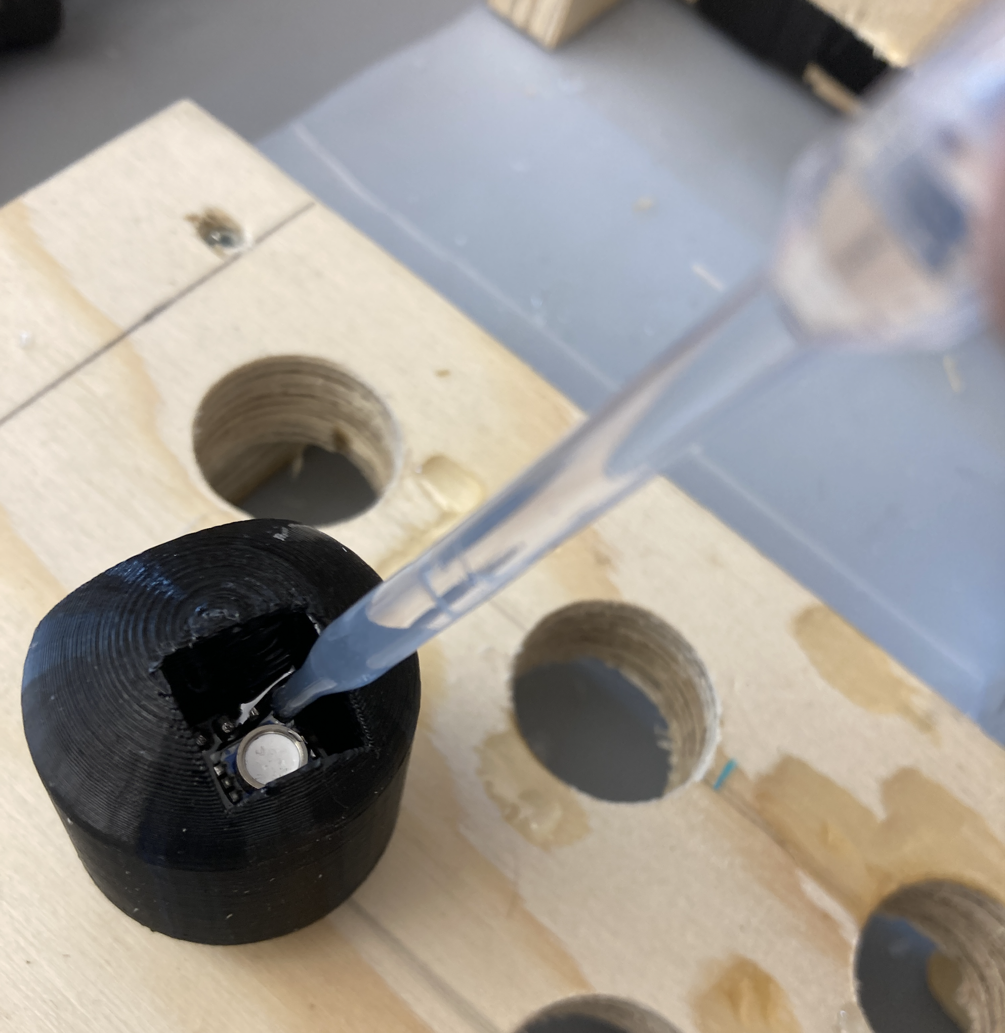
Once the epoxy is bubble free, use a disposable pipette to fill the pressure sensor opening to a level that covers the electronics but without getting epoxy on the white gel membrane of the pressure sensor. Allow the epoxy to cure for 12-24 hours again.
Final Assembly
- Cut a 6” length of 1” diameter PVC. Wash it now if necessary.
- In a well ventilated space (e.g. fume hood, fan in a window, outdoors), attach the completed sensor head to the PVC using PVC cement. Apply the cement all around the small diameter of the sensor head and then insert. Twist to spread the cement.
- Allow the cement to dry for about 30 mins (or according to the instructions on the can).
- Flip the sensor housing so the open end is up and pour about 10g of mixed epoxy inside the housing, down on the inside of the sensor head. This will prevent leaks at the junction of the sensor head with the PVC better than the PVC cement alone.
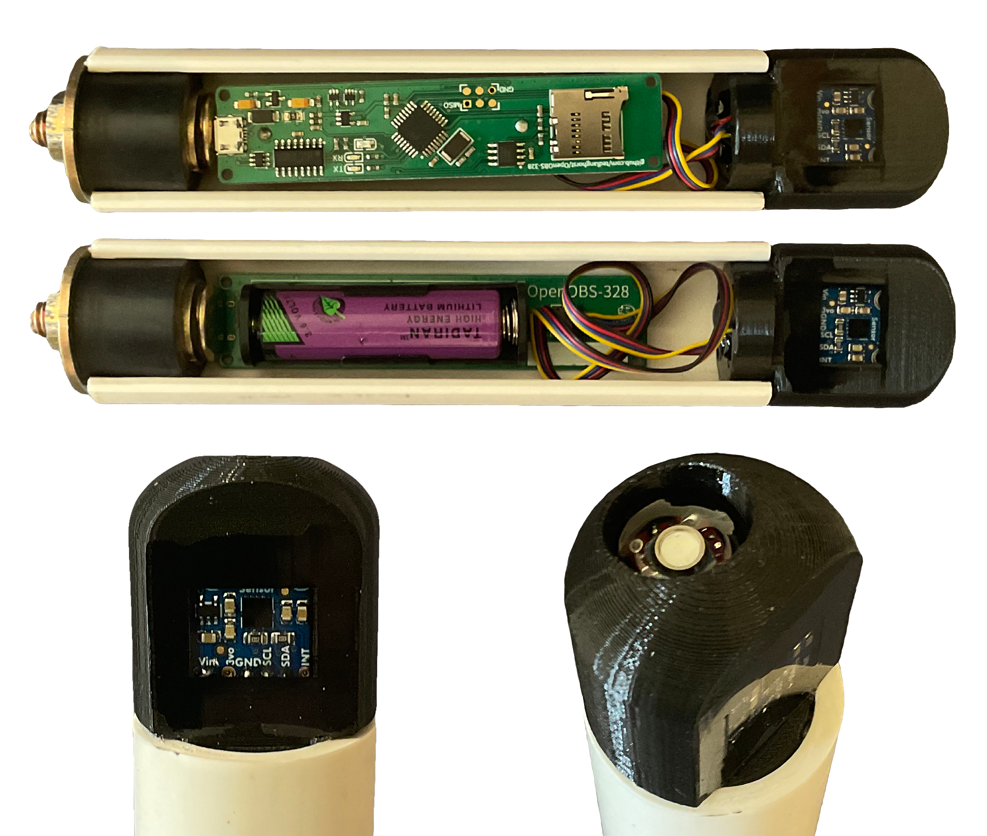 Version 1 of the sensor head pictured. This photo does not include the PVC cement or epoxy that would seal the sensor head in place.
Programming
ISP & Bootloading
When we order new PCBs with microcontrollers on them, they are a blank slate with default configurations and no code running. The bootloader is firmware that we ‘burn’ on the microcontroller that defines some settings and subsequently allows us to upload Arduino code via the USB connection. You can think of this kind of like the BIOS of a regular computer: it doesn’t do much on its own, but it lets us install an operating system and then run programs etc. Because this step sets up the protocol for uploading from USB, we have to send this firmware to the microcontroller through the In System Programming (ISP) connections before we can use the USB connection on the OpenOBS-328.
You can find additional background info here if you want to read more!
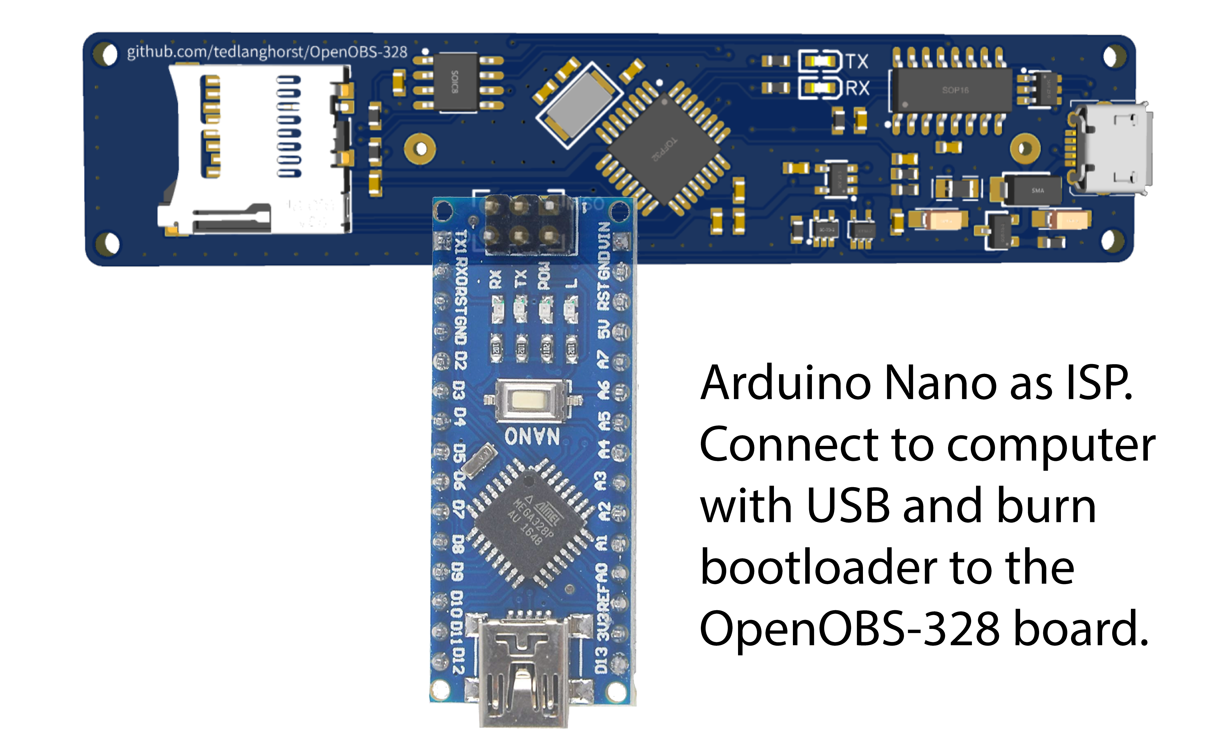
ISP programmer
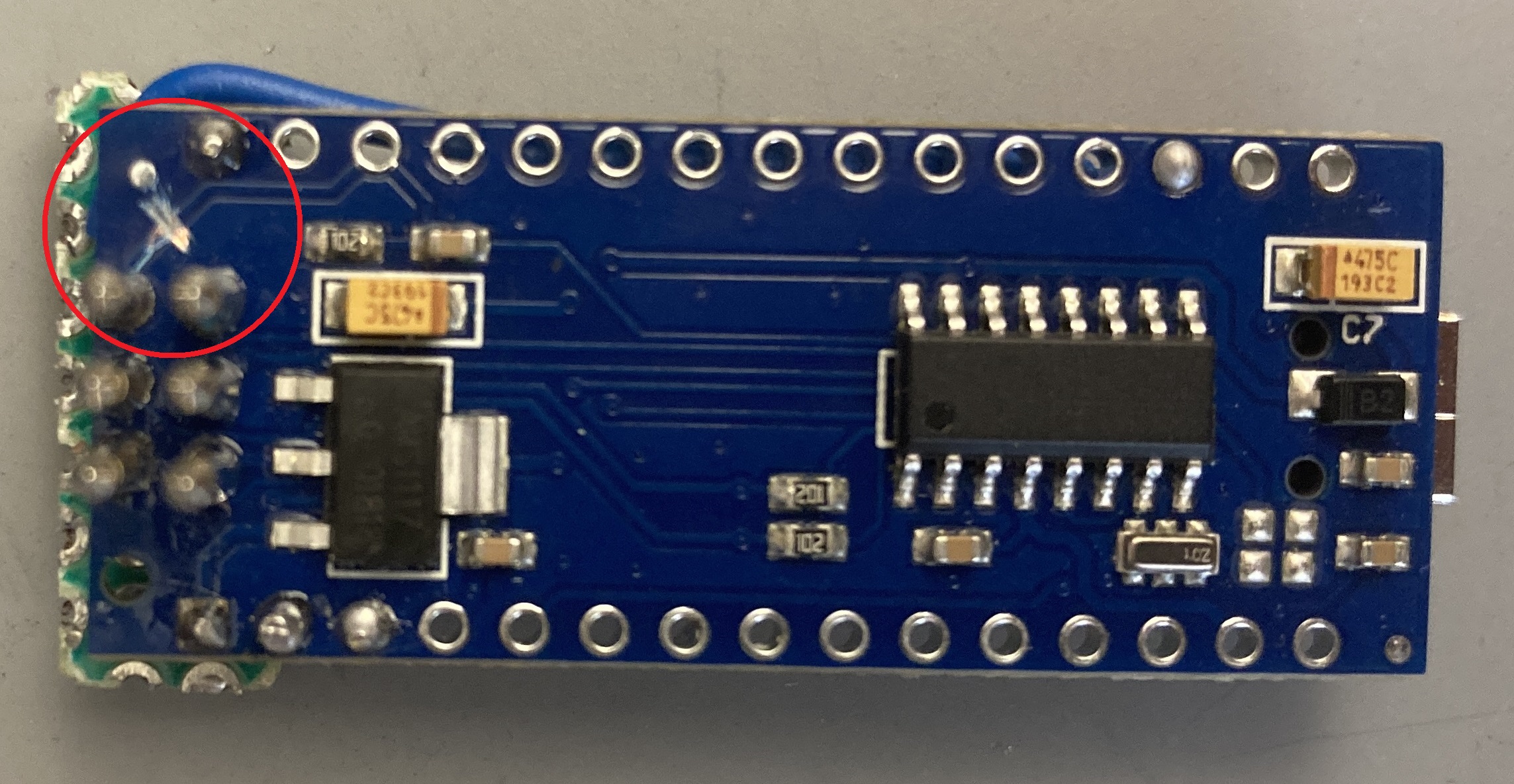
We will use an Arduino Nano that already has a bootloader installed to burn our new device. It will be a lot easier if you find an Arduino Nano that does not have the header pins already soldered in place. In addition to the 6 pogo pin connectors, you will need to attach a wire from pin D10 to the RST pogo and then cut (scratch out) the RST trace on the Nano. The capacitor between ground and reset in the image below can help with stability, but is not always necessary.
Next, make sure the correct board (Arduino Nano) is selected in the IDE (Tools -> Board) and then upload the ArduinoISP sketch (File -> Examples -> ArduinoISP).
| D10 wire | D10 to RST | RST trace cut |
|---|---|---|
 |
 |
 |
Connections
The OpenOBS boards all use the standard AVR ISP 2x3 grid so we can use the customized Arduino Nano from above directly on the pads. The corner holes will help locate the pins, but be careful not to twist too much and break the pins.
⚠️ Never connect the powered ISP programmer to the board while the sensor head is attached. The programmer works at 5V, while the sensor heads are only rated to ~4V max. It likely will not immediately break the sensors but could do damage that will make them less reliable in the future.
 Orientation of the Arduino Nano ISP and the OpenOBS-328
Board options
We have a custom circuit and the standard Arduino board options will not work for us. The next section covers how to add new, custom options to the Arduino IDE.
We will use the MiniCore and MegaCore set of boards for our custom circuits. See the instructions for both under “Board Manager Installation” at the following links for how to make these options available in the Arduino IDE (minicore install link; megacore install link)
Once you have installed the new boards options, you can click on Tools -> Boards -> MiniCore -> ATmega328 (for OpenOBS-328 and the OpenOBS-Iridium sensor) or Tools -> Boards -> MegaCore -> ATmega2560 (for the OpenOBS-Iridium logger) from the top menu. Now, under tools -> boards there will be many new options for our microcontroller. Use the following settings whenever burning the bootloader or uploading new sketches:
Table 1: Board settings for uploading to OpenOBS devices.
| OpenOBS-328 | OpenOBS-Iridium Sensor | OpenOBS-Iridium Logger | |
|---|---|---|---|
| Board | MiniCore -> ATmega328 | MiniCore -> ATmega328 | MegaCore -> ATmega2560 |
| Clock | External 8MHz | ||
| BOD | 2.7V | 2.7V | 4.3V |
| EEPROM | EEPROM retained | ||
| Compiler LTO | LTO enabled | ||
| Variant | 328P/328PA | 328P/328PA | N/A |
| Pinout | N/A | N/A | Arduino MEGA pinout |
| Bootloader | Yes (UART0) | No bootloader | Yes (UART0) |
Burning Booatloader
After selecting the correct board options for the OpenOBS, make sure “Arduino as ISP” is selected under Tools -> Programmer. Connect the ISP programmer pins to the OpenOBS and then go to Tools -> Burn Bootloader. Wait for a message that indicates success and then you’re done! You can now upload sketches over USB.
USB
After installing the Arduino bootloader via the ISP programming, we can now upload code via the micro-USB connection.
Setup
-
If you already have the Arduino IDE and know how to connect and upload code, skip ahead to the next step. Otherwise, download and install the free Arduino IDE and follow this guide to get familiar with the IDE and learn how to upload code.
-
Review the section “Setting board options” earlier in this section and use Table 1 to pick the correct board in the Arduino IDE.
-
Download and unzip the entire github repo for the sensor you are working with to get the latest code and documentation.
-
The Arduino IDE comes with many libraries, and we have packaged several others with the OBS code, but one library needs to be installed separately using the Arduino Library Manager. Search for “SdFat” (by Bill Greiman) and click install.
Firmware
-
Open the correct sensor firmware in the Arduino IDE
-
Check the variables near the top of the script, right after the libraries.
 // Likely variables to change
 #define MS5803_VERSION 5 //comment or remove if you aren't using the pressure sensor
 long sleepDuration_seconds = 0;
 const char contactInfo[] PROGMEM = "If found, please contact XXX@XXX.com";
Most important right now is the MS5803_VERSION variable, which can be either be 2, 5, or 14, depending on the version of the MS5803 pressure sensor you are pairing this logger with. If you are building the device without a pressure sensor, you can remove this line.
⚠️ The sensor version is really important to get right. If it is wrong, the pressure and temperature data will be very hard to recover.
- Upload the sketch to the logger. Watch the IDE status bar for the code to be compiled and uploaded.
❓ If you can’t find the COM port for the OpenOBS, you likely need to install the CH340 USB driver.
-
Open the Serial Monitor (Tools -> Serial Monitor) and verify that the OpenOBS is starting up and communicating. Change the baud rate to 250000 in the bottom right corner of the Serial Monitor if it is not already set.
- If the serial number has not been set, the serial monitor will prompt you to set it now by typing it at the top of the window. If you need to change it in the future, use the sketch titled “reset_serial_number.ino”, follow the prompts in the serial monitor, and then reupload the regular sensor firmware.
Programming with ISP
We can also send our Arduino program to the microcontroller directly through the ISP, rather than installing a bootloader and then programming through USB. The advantage to this method is that we do not need the hardware for a USB connection. We will only use ISP programming for the sensor end of the OpenOBS-Iridium variant, because once we verify the sensor is working, we will encase it in epoxy.
After following the bootloader instructions above, keep the ISP programmer in place and go to Sketch -> Upload Using Programmer to upload the code.